How it is calculated
DIN 5480 splines are named by the reference diameter dB, which is close to the shaft outside diameter, not by the pitch diameter. All splines use one 30° basic rack with addendum 0.45·m and dedendum 0.55·m. The profile shift x·m makes the teeth fit the chosen dB, and the tooth count is picked so that x stays between −0.05 and +0.45. Hub and shaft are centred on the flanks; the tips clear the roots by 0.1·m.
Profile shift x·m = (dB − m·z − 1.1·m) / 2 (−0.05·m ≤ x·m ≤ +0.45·m)
Reference / base Ø d = m·z db = m·z·cos 30°
Shaft tip / root Ø da1 = dB − 0.2·m df1 = dB − 2.2·m (nominal, hobbed)
Hub tip / root Ø da2 = dB − 2·m df2 = dB (nominal, broached)
Tooth thickness at d s = m·(π/2 + 2·x·tan 30°) = hub space width e at zero clearance
ANSI B92.1 (30° flat root side fit, inch): D = N/P Do = (N+1)/P Dre = (N−1.35)/P Di = (N−1)/P Dri = (N+1.35)/P s = π/(2P)
Flank pressure p = 2·T·KA / (dm · h' · L' · z · φ) ≤ p_allow
mean diameter dm = (da1 + da2)/2 = dB − 1.1·m (ANSI: D)
bearing height h' = (da1 − da2)/2 = 0.9·m (ANSI: 0.9/P, Machinery's Handbook) no tip chamfer deducted
load share φ = 0.75 (conservative: Decker; Roloff/Matek-type tables give 0.75 for inner-centred and 0.9 for flank-centred splines)
credited length L' = min(L, 1.3·dB)
Length needed L_req = 2·T·KA / (dm · h' · z · φ · p_allow)
Torque capacity T_cap = min( flank p_allow · dm · h' · L' · z · φ / (2·KA), shaft τ_allow · π·df1³/(16·KA), hub limit from σ_t ≤ allowable )
Shaft torsion at root τ = 16·T·KA / (π·df1³) ≤ 0.58·Re / 1.5
Hub hoop stress (Lamé) p_i = (2·T·KA/dm)·tan 30° / (π·dm·L') σ_t = p_i·(D² + df2²)/(D² − df2²) ≤ Re/1.5 (GJL: Rm/3)
Allowable pressure fixed: 0.9·Re of the weaker part (case-hardened ×1.15, GJL 0.5·Rm) – TorqueMath rule, the same as our Shaft Key page; published
simplified values are often lower (e.g. RoyMech 130 MPa for C45 fixed), DIN 6892 uses fS·fH·Re with safety factors · shifted unloaded: ½ of fixed (TorqueMath rule)
sliding under load: 10.3 / 13.8 / 34.5 MPa (1500 / 2000 / 5000 psi, straight-tooth steel splines, Dudley via Machinery's Handbook; GJS hub given the steel value),
GJL 5 MPa (low end of the 5 – 15 MPa range in German lecture tables)
This is the simplified mean-pressure check used in Roloff/Matek, Decker and Niemann for a first design: the torque is shared by three quarters of the teeth with a uniform pressure over the bearing height and the credited length. The full method of DIN 5466-1 replaces φ and the length cap by circumferential and face load-distribution factors (kφ, kβ) from the torsional and bending stiffness of shaft and hub, checks the tooth root and the shaft notch for fatigue, and handles bending moments and reversing torque. Use that method, or test data, for highly loaded, reversing or long splines. Shaft fatigue at the spline run-out is checked separately in the shaft calculator (Kt for splines about 2.5 – 3 in torsion).
The tip and root diameters are nominal values for the basic profile. Real hubs are broached or shaped and real shafts are hobbed, shaped or cold rolled, and the tool, the tolerance class (for example 9H / 8f) and the deviation series move the root diameters by a few hundredths of a millimetre; DIN 5480-2 gives the inspection dimensions over pins and over k teeth for each size.
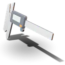 Gear tooth vernier caliper
 Gauge pin set
 Anti-seize assembly paste